
It seems that I can’t avoid periodically ostracizing this page. Welp, let’s try to make it up.
Context: the AS5030 magnetic encoder IC
In a project I’m currently working on (more about it in later posts, perhaps), I needed a halfway decent way of measuring the angular displacement of a small, manually-turnt wheel. I had originally mounted a small mechanical encoder (Bourns PEC11R) into my solution, which yielded about 96 pulses per-revolution (PPR). However, on a long run, contacting encoders are not the best pick for these applications due to mechanical wear.
Searching for a better solution I came across ams’ portfolio of magnetic encoders, which features interesting solutions for contactless position measurement. Amongst them, the AS5030 (datasheet) was the one that best met my requirements, providing an improved 256 PPR. The gist of it is simple: mount the IC, power it up and spin a magnet on top of it. The IC will generate a PWM signal with a pulse width proportional to the magnet’s angle in relation to the chip. Spoiler alert: not any magnet will work! You’ll have to get diametric magnets, such as this little guy here.
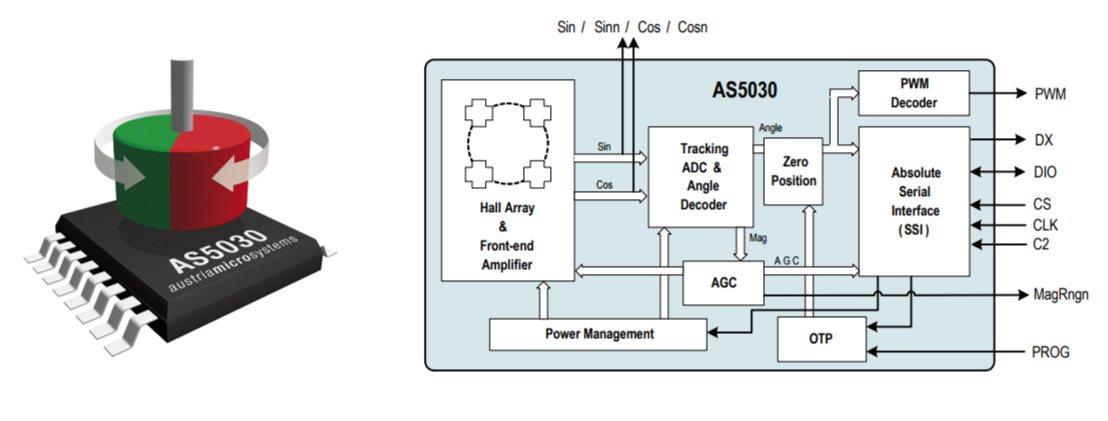
As you may see in the diagram above, the AS5030 also provides a serial interface. The thing, however, is a weird half-duplex SPI that operates on 21-bit long frames, making it odd to use. On top of that, the AS5030 is strictly 5V compatible, which means I would have to level-shift all the signals going to my 3v3 microcontroller. That would just add unnecessary parts and complexity, so I ditched the serial interface and went with PWM (and a resistive divider to shift the voltage for the uC).
The PWM signal frequency is rated at 1.72kHz, but may vary slightly with temperature. The duty cycle encodes the position, going from a spec’d minimum of 2.26us to a spec’d maximum of 578.56us, like shown in the picture below:
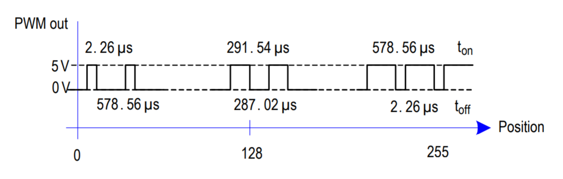
Getting the angular position accurately can be done via the ratio of the duty cycle ($t_{\text{on}}$) and the PWM’s period ($t_{\text{on}} + t_{\text{off}}$), as per the equation supplied in the datasheet:
$\text{angle}[{^\circ}] = \frac{360}{256}\large[\large(257\frac{t_{on}}{t_{\text{on}}+t_{\text{off}}}\large)-1\large]$
ATSAMD21: peripheral bureaucracy
Measuring the pulse-width of a PWM signal is a textbook example of input capture. Capture operations allow you to record a signal edge together with a timestamp directly via hardware, without having to employ any CPU cycles. The vast majority of modern microcontrollers support this feature, and the ATSAMD21E18A employed in this project is no exception.
As we see in the ATSAMD21 datasheet (section 31.2), the TCC peripheral not only supports this sort of operation, but also has a dedicated mode for pulse-width capture, where “period T will be captured into CC0 and the pulse-width $t_p$ into CC1”. Unfortunately, there’s a catch. Usually, capture operations occur entirely within a timer peripheral, which detects the signal’s edge on a dedicated pin an stores the timestamp based on its internal counter. However, to increase flexibility, capture operations in the ATSAMD21 use the External Interrupt (EIC) peripheral to generate an event in the internal Event System (EVSYS), which gets relayed via the internal event channels to the Timer/Counter (TCC) peripheral, in turn triggering the capture. Wait, what? Let me sketch that out:

This certainly allows for a lot more flexibility, not tying the capture operation to a particular pin, since all pins have EIC Interrupt/Event capability. However, configuring it is quite a mouthful (and quite poorly documented, BTW).
Talk is chip, show me the encode
I suck at puns. Ok, so let’s get a bloatw…I mean, ASF-free setup going. In my particular example, I’ll be using pin PA11, tied to EIC channel 4, but again, any pin can be used. Also, I’ll be using EVSYS’s channel 0, but you can use any of the available channels for any event. This will be done in four steps:
|
1 2 3 4 5 6 |
#include <samd21.h> // Register definitions must be included config_tcc(); // Configure the timer config_eic(); // Configure the external interruption config_evsys(); // Configure the event system config_gpio(); // Configure the dedicated pin |
We’ll first configure the timer. It’ll run off the main GCLK (in this case, at 48MHz), counting up from 0 until 0xFFFFFFFF (then wrapping around):
|
1 2 3 4 5 6 7 8 9 10 11 12 13 14 15 16 17 18 19 20 21 22 23 24 25 26 |
void config_tcc() { // Init power and clock buses PM->APBCMASK.reg |= PM_APBCMASK_TCC1; GCLK->CLKCTRL.reg = GCLK_CLKCTRL_ID(TCC1_GCLK_ID) | GCLK_CLKCTRL_CLKEN | GCLK_CLKCTRL_GEN(0); while(GCLK->STATUS.bit.SYNCBUSY); // Reset TCCx TCC1->CTRLA.reg = TCC_CTRLA_SWRST; while(TCC1->SYNCBUSY.bit.SWRST); // Enable capture on all channels (just because) TCC1->CTRLA.reg |= TCC_CTRLA_CPTEN0 | TCC_CTRLA_CPTEN1 | TCC_CTRLA_CPTEN2 | TCC_CTRLA_CPTEN3 | TCC_CTRLA_PRESCALER_DIV1; // Enable event input (TCEIx), Match/Compare event input (MCEIx) and PWP mode TCC1->EVCTRL.reg |= TCC_EVCTRL_TCEI1 | TCC_EVCTRL_MCEI0 | TCC_EVCTRL_MCEI1 | TCC_EVCTRL_EVACT1_PWP; while(TCC1->SYNCBUSY.reg); // Starting TCCx TCC1->CTRLA.bit.ENABLE = 1; while(TCC1->SYNCBUSY.reg); } |
Then, let’s setup the EIC. Sense is set to HIGH, and a tiny helper function configures the channel. Notice how the EVCTRL bit is set, which generates the EIC event:
|
1 2 3 4 5 6 7 8 9 10 11 12 13 14 15 16 17 18 19 20 21 22 23 24 25 26 27 28 |
/* Sense: * None, Rise, Fall, Both, High, Low * 0x0 0x1 0x2 0x3 0x4 0x5 */ void config_eic_channel(int ch, int sense, bool filt) { // Config channel EIC->CONFIG[ch/8].reg &= ~(0xF << 4*(ch%8)); EIC->CONFIG[ch/8].reg |= (0xF & ((filt? 0x8 : 0) | (0x7 & sense))) << 4*(ch%8); // No wake-up EIC->WAKEUP.reg &= ~(1 << ch); // No interrupt EIC->INTENCLR.reg |= 1<<ch; // Generate Event EIC->EVCTRL.reg |= 1<<ch; } void config_eic() { PM->APBAMASK.reg |= PM_APBAMASK_EIC; GCLK->CLKCTRL.reg = GCLK_CLKCTRL_ID(EIC_GCLK_ID) | GCLK_CLKCTRL_CLKEN | GCLK_CLKCTRL_GEN(0); EIC->CTRL.reg = EIC_CTRL_SWRST; while(EIC->CTRL.bit.SWRST && EIC->STATUS.bit.SYNCBUSY); config_eic_channel(11, 4, false); EIC->CTRL.bit.ENABLE = 1; while(EIC->STATUS.bit.SYNCBUSY); } |
Let’s then configure the EVSYS: EIC acts as a event generator on channel 0, and TCC1 is the event’s user (akin to a listener):
|
1 2 3 4 5 6 7 8 9 10 11 12 13 14 15 16 17 18 19 20 21 22 |
void config_evsys() { PM->APBCMASK.reg |= PM_APBCMASK_EVSYS; GCLK->CLKCTRL.reg = GCLK_CLKCTRL_ID(EVSYS_GCLK_ID_0) | GCLK_CLKCTRL_CLKEN | GCLK_CLKCTRL_GEN(0); while(GCLK->STATUS.bit.SYNCBUSY); EVSYS->CTRL.bit.SWRST = 1; while(EVSYS->CTRL.bit.SWRST); // Event receiver EVSYS->USER.reg = EVSYS_USER_CHANNEL(1) | // Set channel n-1 EVSYS_USER_USER(EVSYS_ID_USER_TCC1_EV_1); // Match/Capture 1 on TCC1 // Event channel EVSYS->CHANNEL.reg = EVSYS_CHANNEL_CHANNEL(0) | // Set channel n EVSYS_CHANNEL_PATH_ASYNCHRONOUS | EVSYS_CHANNEL_EVGEN(EVSYS_ID_GEN_EIC_EXTINT_11) | EVSYS_CHANNEL_EDGSEL_BOTH_EDGES; // Detect both edges // Wait channel to be ready while(!EVSYS->CHSTATUS.bit.USRRDY0); // EVSYS is always enabled } |
Last but not least, let’s configure the pin. The PINMUX_PA11A_EIC_EXTINT11 value should be defined in the samd21.h header:
|
1 2 3 4 5 6 7 8 9 10 11 12 13 14 15 16 17 |
void gpio_in(int port, int pin) { PORT->Group[port].DIRCLR.reg = (1 << pin); PORT->Group[port].PINCFG[pin].reg |= PORT_PINCFG_INEN; } void gpio_pmuxen(int port, int pin, int mux) { PORT->Group[port].PINCFG[pin].reg |= PORT_PINCFG_PMUXEN; if (pin & 1) PORT->Group[port].PMUX[pin>>1].bit.PMUXO = mux; else PORT->Group[port].PMUX[pin>>1].bit.PMUXE = mux; } void config_gpio() { gpio_in(0, 11); gpio_pmuxen(0, 11, PINMUX_PA11A_EIC_EXTINT11); } |
That’s it! Your device is now running PWM pulse-width capture on pin PA11, with no CPU cycles being used for it at all.
Now what?
Now that everything’s configured, … Well, make sure the PWM signal is getting to the designated pin. The signal’s pulse-width and period are now constantly being fetched and saved into the CC0 and CC1 registers, respectively. To wrap it up with the AS5030, we can now compute the measured angle with the following function:
|
1 2 3 4 5 6 7 8 |
// Returns an angle between 0 and 3600 (*10, so that no float required) int as5030_read_pos() { int w = TCC1->CC[0].bit.CC; // Pulse width int p = TCC1->CC[1].bit.CC; // Period if(w == 0 || p == 0) return -1; // Avoid destroying the universe as we know it return (3600*(((257*w)/p)-1)/256); } |
This function returns angles x10, (i.e. 15.4° = 154), so that no float support needs to be added (which can eat a lot of Flash on smaller devices). It’s also enough to properly deal with the AS5030’s 1.4° resolution.
Best part? It actually works:
You can optionaly use the TCC_INTFLAG_MC1 interruption if you don’t want to poll the registers for changes. Yeah.
’til next time.