
So, just a little throwback. I’ve always wanted to build a 3D printer (or any CNC machine, for that matter) on my own. Around two years ago, I’ve decided to take that desire seriously, and started doing some research on designs for 3D Printers and CNC mills. After some googlin’ I set myself with goals of building a machine that:
- Had a large working volume (around 35 x 35 x 30 cm)
- Enabled fast prints (80mm/s and faster)
- Was cheap-ish (I live in Brazil, and getting proper mechanical/electrical components here is insanely expensive)
- Enabled both 3D printing and milling (at least of softer woods and plastics)
So, pretty much a godmode machine – what every engineer desires, but only unexperienced newbies strive for. The last point there is specially tricky. Milling and printing are very different activities, that shape machines in very different ways.
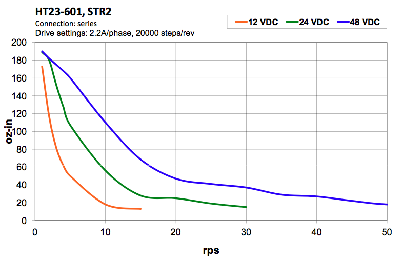
Milling usually requires more robust and rigid machines that can handle the high (read: tremendous) opposing forces applied on the end-effector (the cutting tool). Cutting speeds are relatively low, and depend on the material that’s being milled. Arrangements with a moving portal carrying the Z gantry are quite common, since they allow the workpiece to remain stationary, and provide a stable frame. Such configuration, on the other hand, means that A LOT of mass has to be constantly moved around: the motors for the Y and Z axis, the portal, all mechanical components attached, and so on – which constraints aggressive acceleration profiles. Partially because of that, CNC mills are normally leadscrew driven. Most of such leadscrews present pitches in the 2 to 5 mm range, allowing increased torque transmission and movement precision, but reducing the overall speeds. From the beginning of this project, I knew that I would be working with a 12V power supply and NEMA 23 steppers – the most cost-effective solution available to me. From the graph below it’s easy to see that, even with such a 5mm pitch leadscrew, achieving speeds of around 80-100mm/s on that configuration is hard/impossible. Leadscrews were a no-go.
3D Printing behaves quite differently. During a print, the end-effector (hot-end) moves practically freely, with almost no opposing forces whatsoever. Machines are built with a minimum rigidity to prevent vibration or backlash in the moving parts, but the goal usually is to reduce the inertia of the moving elements. Classical setups include floating Y axis, and are often built out of off-the-shelf screws and 3D printed parts, MDF sheets, etc. Timing belts are the default means for movement transmission, enabling higher speeds. This comes at the cost of reducing torque, precision and general frame rigidity – but good print qualities are generally attainable. Note: I’m clearly addressing low-cost, desktop hobbyist printers in this description.
My faith on joining those two worlds in a single machine grew after I saw the Shapeoko 2 milling aluminum. The Shapeoko 2 is a desktop-ish CNC mill that is built out of many elements that figure on a regular 3D printer: NEMA 17 motors, GT2 belts, makerslides, and so on. With all that in mind, I started designing my machine. After a couple weeks, I came up with a design that made me happy:
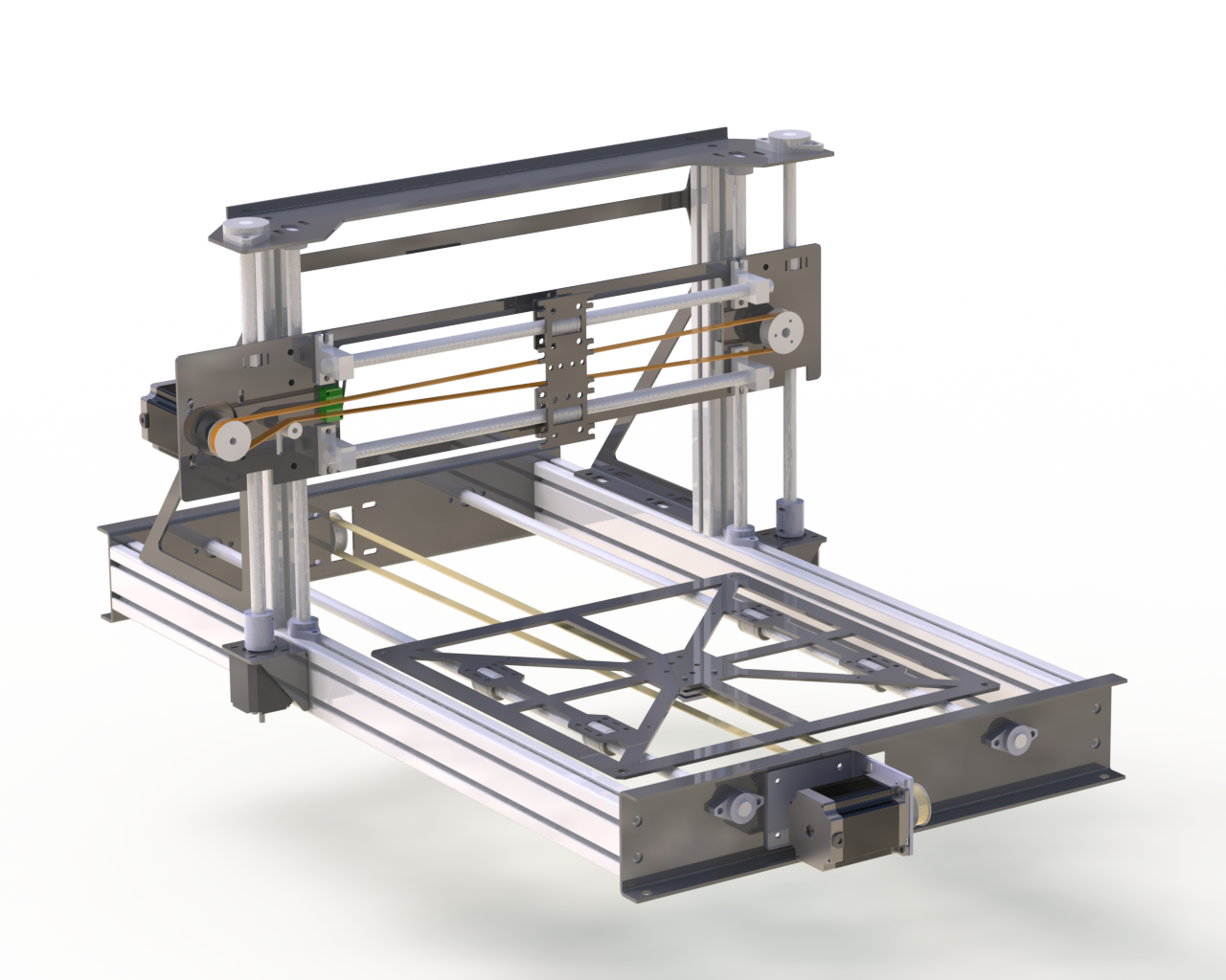
Yeah, it ended up looking an awful lot like a Prusa i3 on steroids. But I took it as a good sign, that a lot of thinking took me to the same tested-and-proven design. Though I could’ve spared the time. And now the CoreXY looks darn interesting. Whatever. Anyway, I had no 3D printer available at the time, so I struggled to keep all the custom parts “laser-cuttable”.
After purchasing all the couplers, screws, belts, pulleys, aluminum profiles and other bits, I sent the designs to be laser cut on 3mm aluminum sheets. All parts came in; the build started.

As the pic above shows, I had originally chosen a different arrangement for the Z axis: each screw was coplanar to only one linear rail (instead of being coplanar to both simultaneously). Soon enough I saw that the smallest wobble of the screw would cause the whole gantry to wobble along, rendering even the coarsest prints impossible. Couple more days in front of SolidWorks and the mistake was fixed [the rendering above is the fixed version]. There, no one saw it. Move along.
A couple parts for the fix had to be recut. They came in, and the result soon popped out:
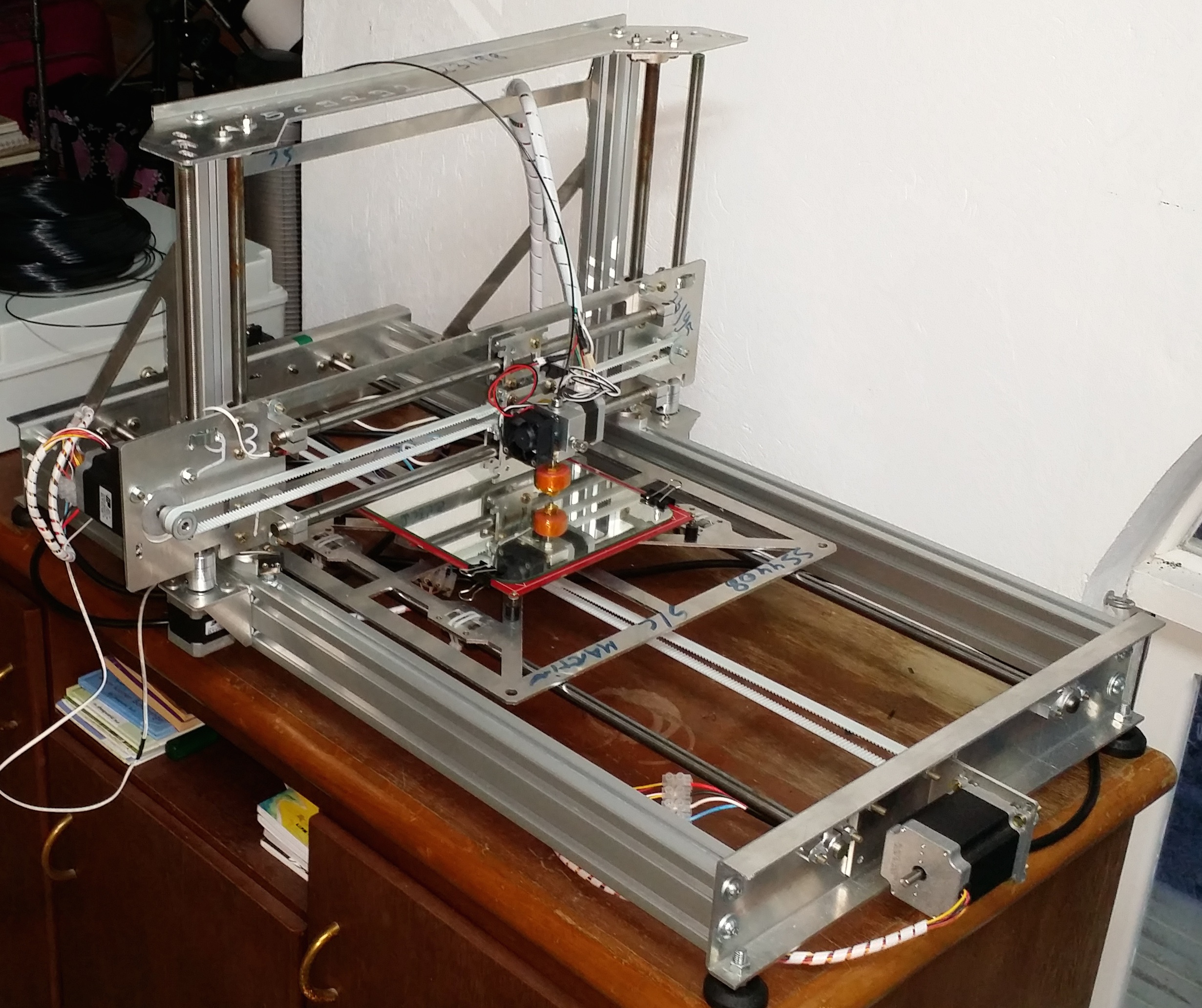
Everything looked OK. Rigid enough for me. Next up; assembling the electronics. I’ll leave that for a next post. I’ll also put the CAD files up anytime soon.
Ah, I’ve obviously ‘Instagramed’ it. “The experience is not complete if you don’t post it on Instagram”, said someone once.
’til next time.