
Having finished the mechanical assembly of my printer, it was time to assemble the electronics to get everything moving.
As I stated in the previous post, my intention to build a large-volume printer/mill made me choose NEMA 23 stepper motors for the X and Y axis. Larger motors would be capable of handling greater forces and more aggressive acceleration profiles, that regular NEMA 17s would not. After some research, I purchased 2 Applied Motion’s HT23-601. With a holding torque a little below the 2N.m, I was (and still am) pretty sure that those motors would be overkill (which isn’t a bad thing). For the Z axis I got 2 Applied Motion’s HT17-275 – good quality NEMA 17s that would do the job.
The thing with the larger NEMA 23s is their current requirements. The maximum current for the HT23’s bipolar parallel arrangement is rated around the 4.3A. Regular 3D printer stepper drivers, such as the A498 or the DRV8825 handle up to 2.2A (with active cooling!), so they are way off the range. Also, keeping the ICs operating constantly at their max is guaranteed to greatly reduce their lifespan. Operating the NEMA 23s on lower currents also wasn’t an option, simply because I wouldn’t be able to make the most out of them. At that point, I thought I’d have to get industrial stepper drives that would leave my pocket echoing. Luckily enough, Google (oh, my dear) pointed me to the Powerlolu, a 10A stepper drive that still falls in the $50 range.
After getting the Powerlolus and my RAMPS 1.4 (the printer’s control board), the wiring-fun started. I quickly noticed that, even for small test setups, the amount of wires hanging all over the place was increasing rapidly. Besides being annoying, messy wiring is the best spice for cooking your components. In order to prevent that, I mounted everything in a proper enclosure box, and tried to keep the wires, buses and connectors as neatly organized as possible. The result, after dozens of boring hours, was worth it:
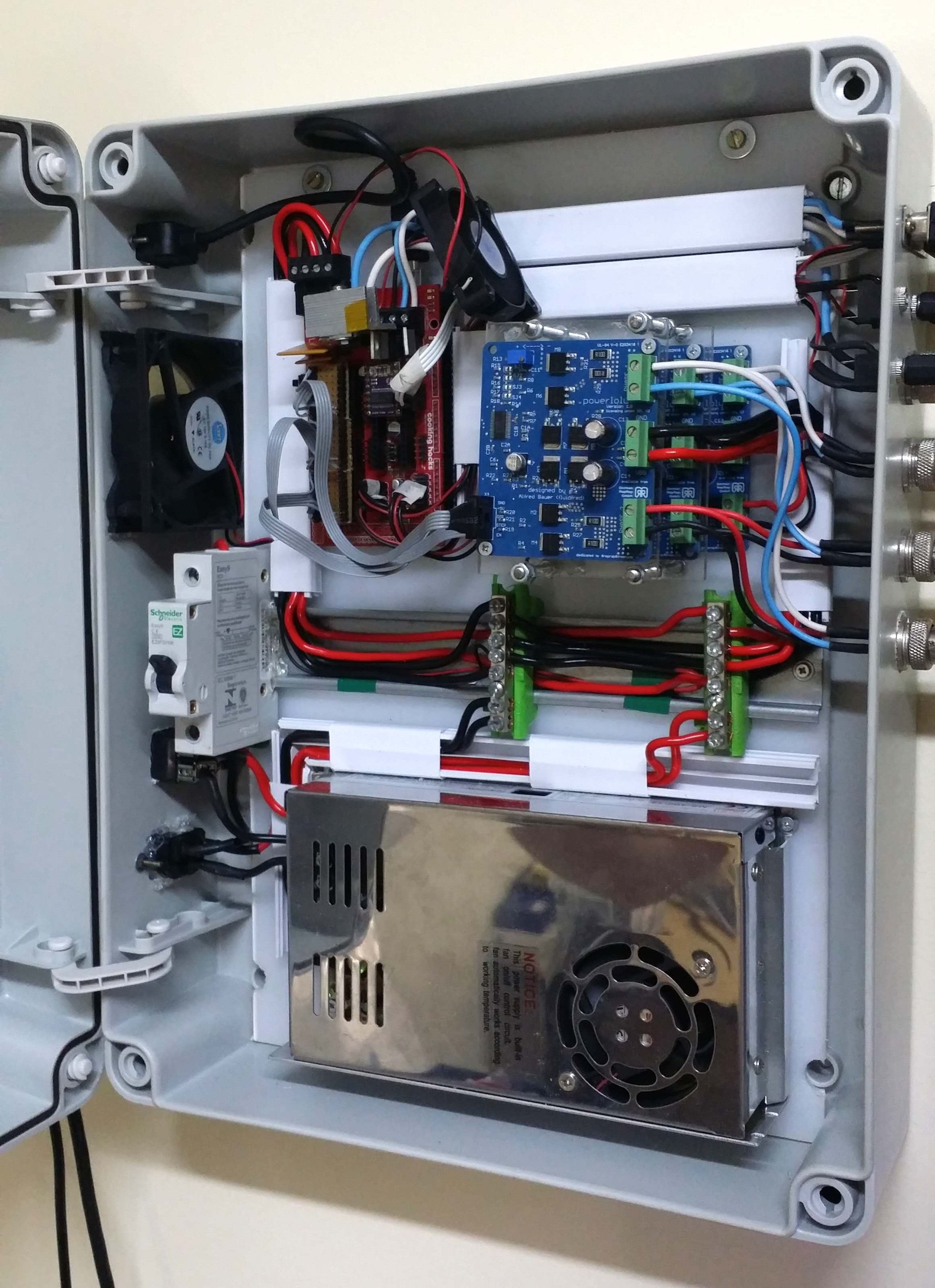
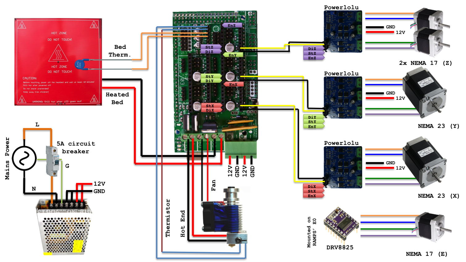
For the record, there goes a somewhat simplified wiring diagram of the box’ contents. I’m using a 12V/33A power supply, so I added a 5A circuit breaker on the mains’ power input to avoid burning down my house if anything went wrong.
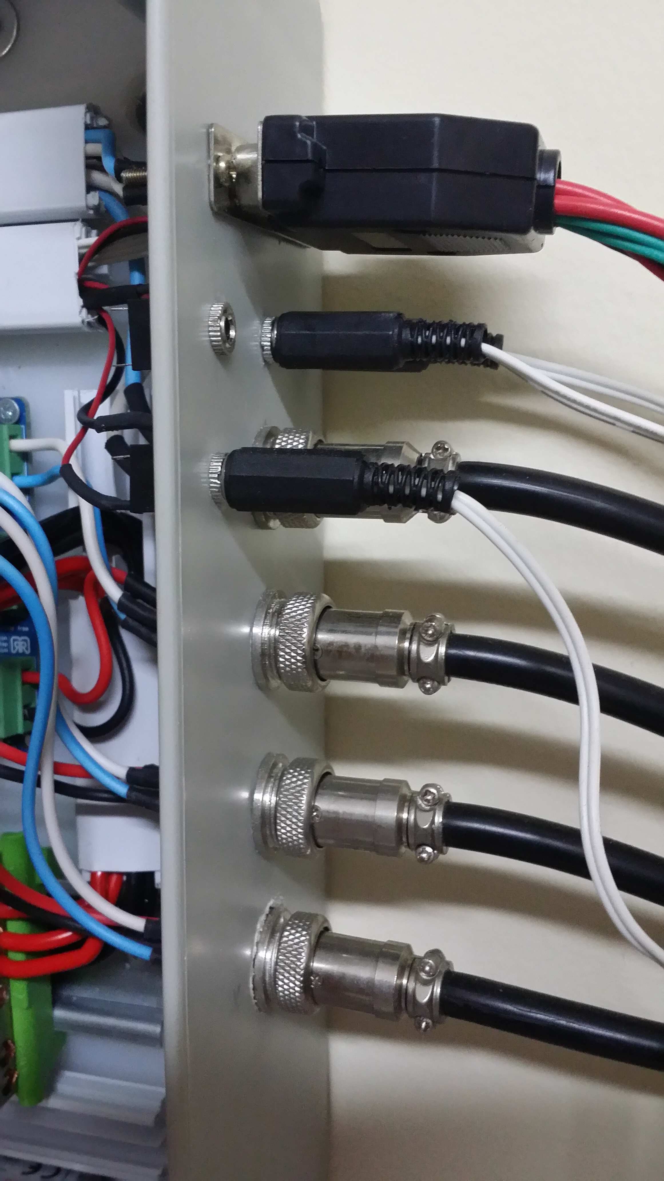
As the picture below displays, the components (motors, hot end, heat-bed, etc.) are attached via connectors mounted on the side of the box. This makes the connection more robust to vibration and eventual pulls. For the stepper motors, I used 3 4-pin circular connectors (the four, from the bottom). They resemble XLR connectors with extra pins and screw caps, and I’m not really sure how they’re correctly called. The heat-bed also uses such connector, in it’s 2-pin version. Such connectors handle up to 5A per pin. Though they can’t support the Powerlolu’s full 10A, they were (sadly) the most cost-effective solution I found. The bed’s thermistor and the endstops are connected to the RAMPS via P2 audio jacks. Lastly, a DB-25 plug handles all the wiring for the extruder and hot-end: stepper motor wiring, hot-end cartridge, thermistor and fans.
Finishing up, a sideways view of the closed box, showing the USB plug, a fan, the power switch and the mains’ power input.

’til next time.